Simulation Approach
The morl4water framework is built on the assumption that any river system to be simulated can be represented by a structured combination of nodes and flows. Each major component of the system—such as reservoirs, power plants, irrigation districts, etc.—is represented as a “node” with unique attributes and behaviors tailored to that element. These nodes are then interconnected by “flows,” which direct water movement between nodes, enabling the construction of complex river architectures.
To showcase an example have a look at the picture below:
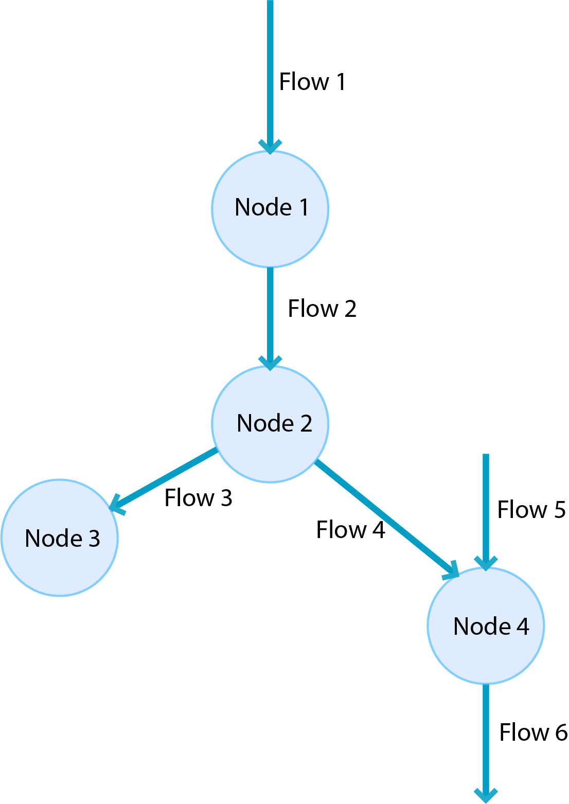
It’s important to note that multiple flows can converge at a single node, and multiple flows can also diverge from it. Additionally, there are different types of nodes and flows, each serving unique functions within the river system. The diagram below illustrates how all elements within a river system are classified.
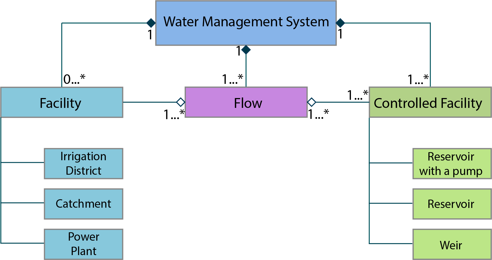
All yellow boxes represent classes implemented within the morl4water framework. The Facility and ControlledFacility classes are always used as superclasses for other facility-related classes. Similarly, the Flow class serves as a superclass for both Inflow and Outflow, although instances of the Flow class itself are also frequently used. To clarify the purpose of each element:
Facility (classes over which RL agent has no control over):
Catchment - A region where rainfall is naturally gathered by the landscape, effectively adding water to the system and resulting in a net gain.
Irrigation District - An area where water is consumed and water demand is to be met.
Power Plant - Place where hydropwer is produced.
Controlled Facility (classes over which RL agent has control over):
Reservoir - stores water and releases it based on the RL action.
Reservoir with Pump - stores water and releases it based on the RL action. It can also pump water against its natural flow.
Weir - It can seperate river flow into 2 seperate flows with different flow rate based on the RL action. It does not store water.
Flow:
Inflow - Flow which introduces water to the system based on the data file of water flow rates.
Flow - Flow connecting two nodes (two river elements) allowing water to go through the system.
Outflow - Flow which simply has no destination.
Time in the Simulation
A clear understanding of how time is handled in the simulation is essential for grasping its mechanics. For each simulation, the user needs to set four key time-related parameters:
start_date - The date when the simulation should start.
timestep_size - Time between different RL Agent’s actions usually a month.
integration_timestep_size - Time determining the shorter state updates within
timestep_size.max_episode_steps - Number of steps to end an episode. It tells how many
timestep_sizeto perform before ending the simulation.
The simulation is structured so that when an RL Agent takes an action, this action is applied consistently over the duration specified by timestep_size. During this period, each river element, such as facilities and flows, is updated at intervals defined by integration_timestep_size (typically spanning several hours) until the end of the current timestep_size. Afterward, the RL agent selects a new action based on the updated states of these elements.
Each river element is updated individually and sequentially within the timestep_size, ensuring that all elements are processed in a specific order. This approach means that, as the simulation enters a new timestep_size, an exemplary facility (node) is updated step-by-step at integration_timestep_size intervals until the end of this timestep_size. Only then a flow leaving from that facility can be subsequently updated.